MASTERY · MATHEMATICS

06-5 应用梅森增益公式求传递函数-1

826 WORDS4 MIN READ#考研

06-5 应用梅森增益公式求传递函数-1

课程总览

本节课适用对象

  • 所有学生

本节课所授知识点

  • 应用梅森增益公式求系统传递函数

重要提示

  • 系统结构越复杂,“信号分支法”的优势越大

随堂练习:应用梅森增益公式求传递函数(1)

例 1

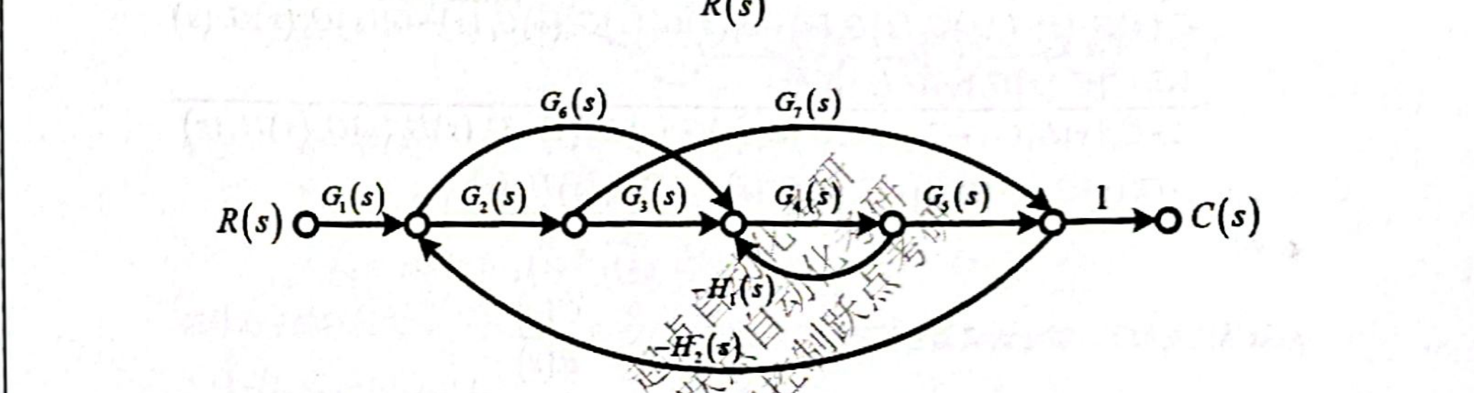
系统信号流图如下,求系统传递函数 C(s)R(s)\frac{C(s)}{R(s)}

06-5_p141_fig01.png

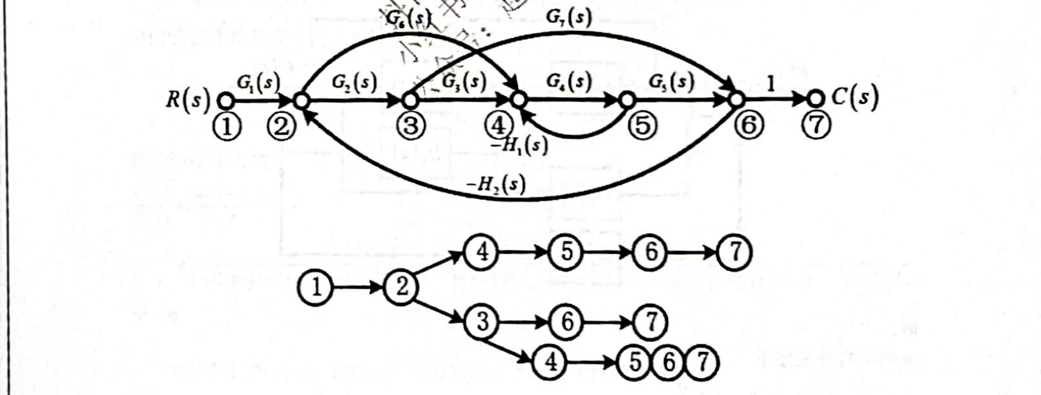
分析: 根据“信号分支法”寻找前向通路与回路(该部分不体现在答案中)

06-5_p141_fig02.png

解:

单回路有四个,即 L1=G4(s)H1(s),L2=G2(s)G3(s)G4(s)G5(s)H2(s)L_1 = -G_4(s)H_1(s), \quad L_2 = -G_2(s)G_3(s)G_4(s)G_5(s)H_2(s) L3=G4(s)G5(s)G6(s)H2(s),L4=G2(s)G7(s)H2(s)L_3 = -G_4(s)G_5(s)G_6(s)H_2(s), \quad L_4 = -G_2(s)G_7(s)H_2(s)

两个互不接触的回路有一组,即 L1L4L_1 L_4

信号流图的特征式为

Δ=1(L1+L2+L3+L4)+L1L4=1+G4(s)H1(s)+G2(s)G3(s)G4(s)G5(s)H2(s)+G4(s)G5(s)G6(s)H2(s)+G2(s)G7(s)H2(s)+G2(s)G4(s)G7(s)H1(s)H2(s)\begin{aligned} \Delta &= 1 - (L_1 + L_2 + L_3 + L_4) + L_1 L_4 \\ &= 1 + G_4(s)H_1(s) + G_2(s)G_3(s)G_4(s)G_5(s)H_2(s) + G_4(s)G_5(s)G_6(s)H_2(s) \\ &\quad + G_2(s)G_7(s)H_2(s) + G_2(s)G_4(s)G_7(s)H_1(s)H_2(s) \end{aligned}

前向通路增益及其余因子式分别为

P1=G1(s)G2(s)G3(s)G4(s)G5(s),Δ1=1P2=G1(s)G4(s)G5(s)G6(s),Δ2=1P3=G1(s)G2(s)G7(s),Δ3=1+G4(s)H1(s)\begin{aligned} P_1 &= G_1(s)G_2(s)G_3(s)G_4(s)G_5(s), & \Delta_1 &= 1 \\ P_2 &= G_1(s)G_4(s)G_5(s)G_6(s), & \Delta_2 &= 1 \\ P_3 &= G_1(s)G_2(s)G_7(s), & \Delta_3 &= 1 + G_4(s)H_1(s) \end{aligned}

系统的传递函数为

C(s)R(s)=P1Δ1+P2Δ2+P3Δ3Δ=G1(s)G2(s)G3(s)G4(s)G5(s)+G1(s)G4(s)G5(s)G6(s)+G1(s)G2(s)G7(s)+G1(s)G2(s)G4(s)G7(s)H1(s)1+G4(s)H1(s)+G2(s)G3(s)G4(s)G5(s)H2(s)+G4(s)G5(s)G6(s)H2(s)+G2(s)G7(s)H2(s)+G2(s)G4(s)G7(s)H1(s)H2(s)\begin{aligned} \frac{C(s)}{R(s)} &= \frac{P_1\Delta_1 + P_2\Delta_2 + P_3\Delta_3}{\Delta} \\ &= \frac{\begin{aligned}&G_1(s)G_2(s)G_3(s)G_4(s)G_5(s) + G_1(s)G_4(s)G_5(s)G_6(s) + G_1(s)G_2(s)G_7(s) \\ &+ G_1(s)G_2(s)G_4(s)G_7(s)H_1(s)\end{aligned}}{\begin{aligned}&1 + G_4(s)H_1(s) + G_2(s)G_3(s)G_4(s)G_5(s)H_2(s) + G_4(s)G_5(s)G_6(s)H_2(s) \\ &+ G_2(s)G_7(s)H_2(s) + G_2(s)G_4(s)G_7(s)H_1(s)H_2(s)\end{aligned}} \end{aligned}

例 2

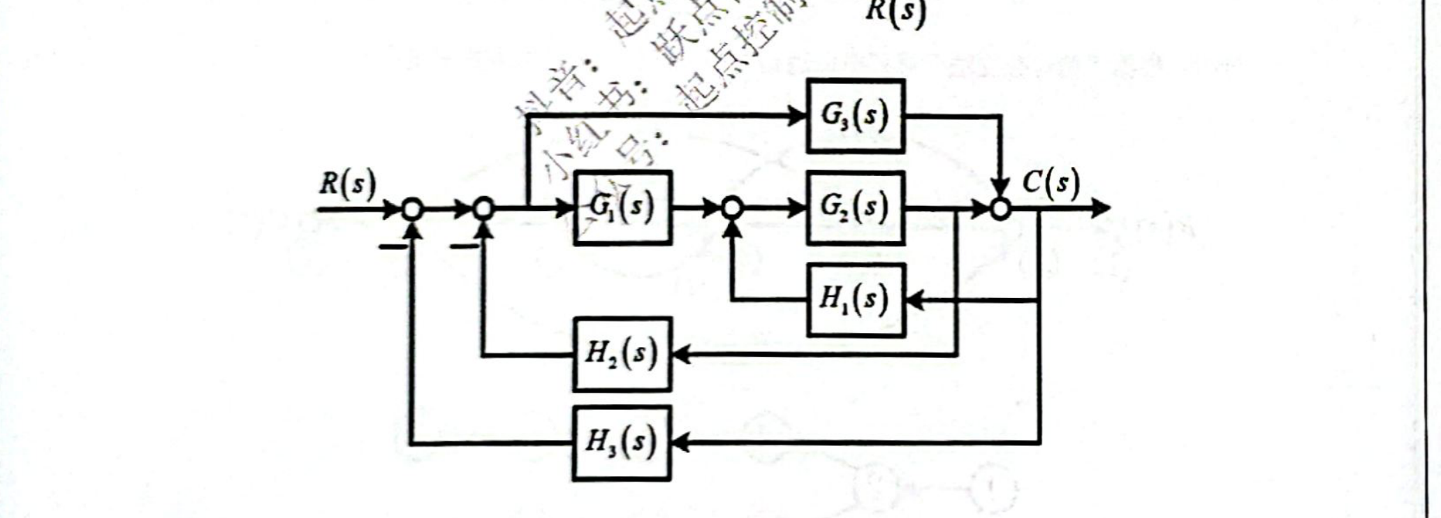
系统结构图如下,试绘制其信号流图,并求系统传递函数 C(s)R(s)\frac{C(s)}{R(s)}

06-5_p142_fig01.png

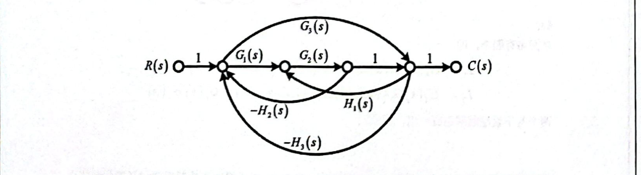
解: 绘制信号流图如下:

06-5_p142_fig02.png

分析: 根据“信号分支法”寻找前向通路与回路(该部分不体现在答案中)

06-5_p143_fig01.png

单独回路有五个,即 L1=G1(s)G2(s)H2(s),L2=G2(s)H1(s),L3=G3(s)H3(s)L_1 = -G_1(s)G_2(s)H_2(s), \quad L_2 = G_2(s)H_1(s), \quad L_3 = -G_3(s)H_3(s) L4=G1(s)G2(s)H3(s),L5=G2(s)G3(s)H1(s)H2(s)L_4 = -G_1(s)G_2(s)H_3(s), \quad L_5 = -G_2(s)G_3(s)H_1(s)H_2(s)

信号流图的特征式为

Δ=1(L1+L2+L3+L4+L5)=1+G1(s)G2(s)H2(s)G2(s)H1(s)+G3(s)H3(s)+G1(s)G2(s)H3(s)+G2(s)G3(s)H1(s)H2(s)\begin{aligned} \Delta &= 1 - (L_1 + L_2 + L_3 + L_4 + L_5) \\ &= 1 + G_1(s)G_2(s)H_2(s) - G_2(s)H_1(s) + G_3(s)H_3(s) + G_1(s)G_2(s)H_3(s) + G_2(s)G_3(s)H_1(s)H_2(s) \end{aligned}

前向通路增益及其余因子式分别为

P1=G1(s)G2(s),Δ1=1P2=G3(s),Δ2=1\begin{aligned} P_1 &= G_1(s)G_2(s), & \Delta_1 &= 1 \\ P_2 &= G_3(s), & \Delta_2 &= 1 \end{aligned}

系统的传递函数为

C(s)R(s)=P1Δ1+P2Δ2Δ=G1(s)G2(s)+G3(s)1+G1(s)G2(s)H2(s)G2(s)H1(s)+G3(s)H3(s)+G1(s)G2(s)H3(s)+G2(s)G3(s)H1(s)H2(s)\begin{aligned} \frac{C(s)}{R(s)} &= \frac{P_1\Delta_1 + P_2\Delta_2}{\Delta} \\ &= \frac{G_1(s)G_2(s) + G_3(s)}{1 + G_1(s)G_2(s)H_2(s) - G_2(s)H_1(s) + G_3(s)H_3(s) + G_1(s)G_2(s)H_3(s) + G_2(s)G_3(s)H_1(s)H_2(s)} \end{aligned}

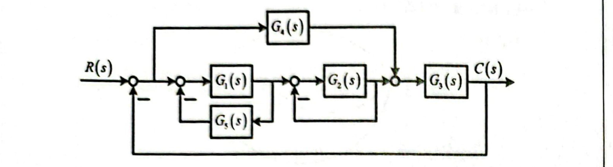
例 3

系统结构图如下,试绘制其信号流图,并求系统传递函数 C(s)R(s)\frac{C(s)}{R(s)}

06-5_p143_fig02.png

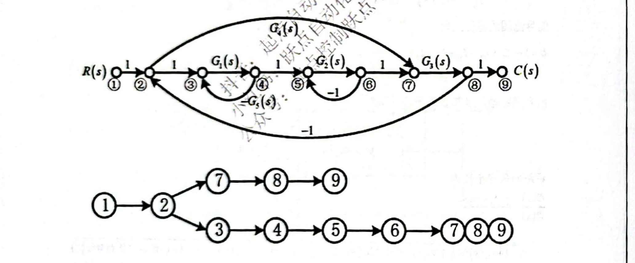
解: 绘制信号流图如下:

06-5_p144_fig01.png

分析: 根据“信号分析法”寻找前向通路与回路(该部分不体现在答案中)

06-5_p144_fig02.png

单独回路有四个,即 L1=G1(s)G5(s),L2=G2(s),L3=G1(s)G2(s)G3(s),L4=G3(s)G4(s)L_1 = -G_1(s)G_5(s), \quad L_2 = -G_2(s), \quad L_3 = -G_1(s)G_2(s)G_3(s), \quad L_4 = -G_3(s)G_4(s)

两个互不接触的回路有三组,即 L1L2,L1L4,L2L4L_1 L_2, \quad L_1 L_4, \quad L_2 L_4

三个互不接触的回路有一组,即 L1L2L4L_1 L_2 L_4

信号流图的特征式为

Δ=1(L1+L2+L3+L4)+(L1L2+L1L4+L2L4)L1L2L4=1+G1(s)G5(s)+G2(s)+G1(s)G2(s)G3(s)+G3(s)G4(s)+G1(s)G2(s)G5(s)+G1(s)G3(s)G4(s)G5(s)+G2(s)G3(s)G4(s)+G1(s)G2(s)G3(s)G4(s)G5(s)\begin{aligned} \Delta &= 1 - (L_1 + L_2 + L_3 + L_4) + (L_1 L_2 + L_1 L_4 + L_2 L_4) - L_1 L_2 L_4 \\ &= 1 + G_1(s)G_5(s) + G_2(s) + G_1(s)G_2(s)G_3(s) + G_3(s)G_4(s) + G_1(s)G_2(s)G_5(s) \\ &\quad + G_1(s)G_3(s)G_4(s)G_5(s) + G_2(s)G_3(s)G_4(s) + G_1(s)G_2(s)G_3(s)G_4(s)G_5(s) \end{aligned}

前向通路增益及其余因子式分别为

P1=G1(s)G2(s)G3(s),Δ1=1P2=G3(s)G4(s),Δ2=1+G1(s)G5(s)+G2(s)+G1(s)G2(s)G5(s)\begin{aligned} P_1 &= G_1(s)G_2(s)G_3(s), & \Delta_1 &= 1 \\ P_2 &= G_3(s)G_4(s), & \Delta_2 &= 1 + G_1(s)G_5(s) + G_2(s) + G_1(s)G_2(s)G_5(s) \end{aligned}

系统的传递函数为

C(s)R(s)=P1Δ1+P2Δ2Δ=G1(s)G2(s)G3(s)+G3(s)G4(s)+G1(s)G3(s)G4(s)G5(s)+G2(s)G3(s)G4(s)+G1(s)G2(s)G3(s)G4(s)G5(s)1+G1(s)G5(s)+G2(s)+G1(s)G2(s)G3(s)+G3(s)G4(s)+G1(s)G2(s)G5(s)+G1(s)G3(s)G4(s)G5(s)+G2(s)G3(s)G4(s)+G1(s)G2(s)G3(s)G4(s)G5(s)\begin{aligned} \frac{C(s)}{R(s)} &= \frac{P_1\Delta_1 + P_2\Delta_2}{\Delta} \\ &= \frac{\begin{aligned}&G_1(s)G_2(s)G_3(s) + G_3(s)G_4(s) + G_1(s)G_3(s)G_4(s)G_5(s) + G_2(s)G_3(s)G_4(s) \\ &+ G_1(s)G_2(s)G_3(s)G_4(s)G_5(s)\end{aligned}}{\begin{aligned}&1 + G_1(s)G_5(s) + G_2(s) + G_1(s)G_2(s)G_3(s) + G_3(s)G_4(s) + G_1(s)G_2(s)G_5(s) \\ &+ G_1(s)G_3(s)G_4(s)G_5(s) + G_2(s)G_3(s)G_4(s) + G_1(s)G_2(s)G_3(s)G_4(s)G_5(s)\end{aligned}} \end{aligned}

例 4

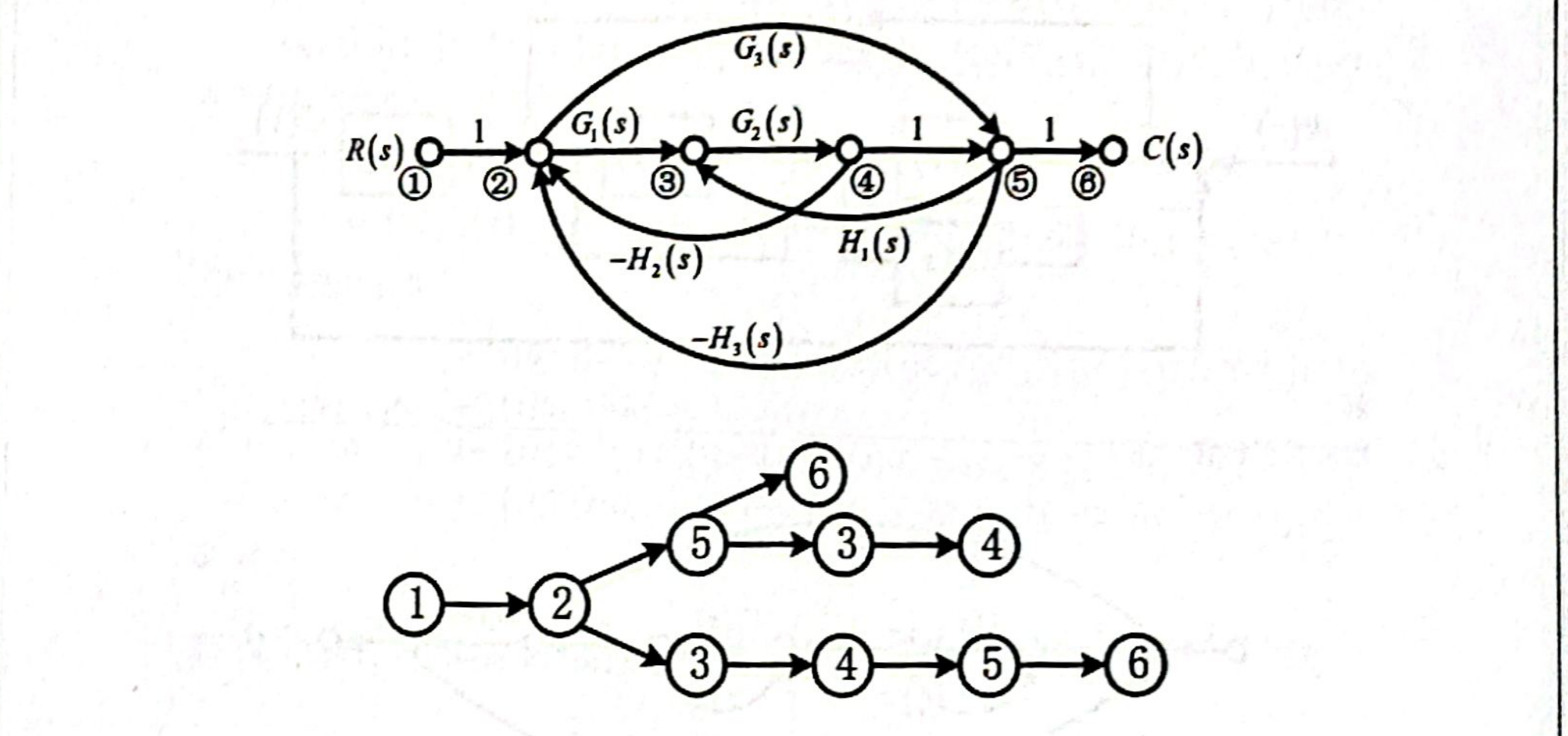
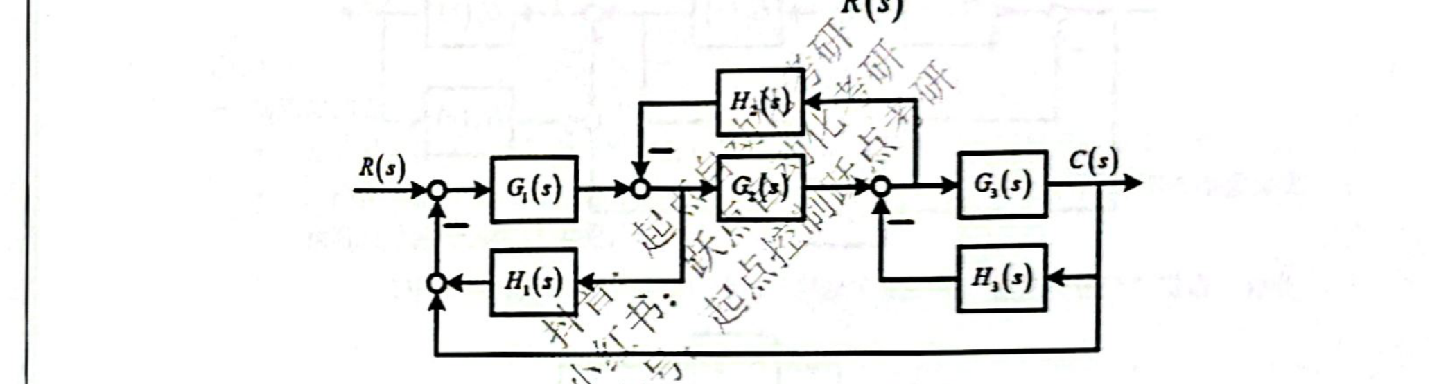
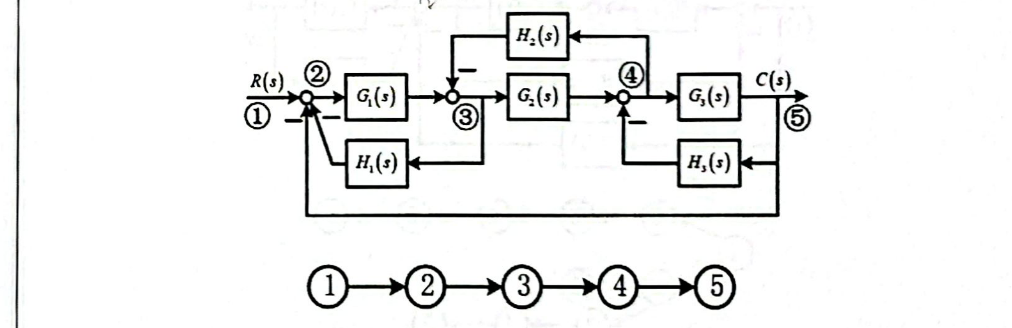
系统结构图如下,试用梅森增益公式求系统传递函数 C(s)R(s)\frac{C(s)}{R(s)}

06-5_p145_fig01.png

分析: 根据“信号分支法”寻找前向通路与回路(该部分不体现在答案中)

06-5_p145_fig02.png

解:

单独回路有四个,即 L1=G1(s)H1(s),L2=G2(s)H2(s),L3=G3(s)H3(s),L4=G1(s)G2(s)G3(s)L_1 = -G_1(s)H_1(s), \quad L_2 = -G_2(s)H_2(s), \quad L_3 = -G_3(s)H_3(s), \quad L_4 = -G_1(s)G_2(s)G_3(s)

两个互不接触的回路有一组,即 L1L3L_1 L_3

信号流图的特征式为

Δ=1(L1+L2+L3+L4)+L1L3=1+G1(s)H1(s)+G2(s)H2(s)+G3(s)H3(s)+G1(s)G2(s)G3(s)+G1(s)G3(s)H1(s)H3(s)\begin{aligned} \Delta &= 1 - (L_1 + L_2 + L_3 + L_4) + L_1 L_3 \\ &= 1 + G_1(s)H_1(s) + G_2(s)H_2(s) + G_3(s)H_3(s) + G_1(s)G_2(s)G_3(s) + G_1(s)G_3(s)H_1(s)H_3(s) \end{aligned}

前向通路增益及其余因子式分别为 P1=G1(s)G2(s)G3(s),Δ1=1P_1 = G_1(s)G_2(s)G_3(s), \quad \Delta_1 = 1

系统的传递函数为

C(s)R(s)=P1Δ1Δ=G1(s)G2(s)G3(s)1+G1(s)H1(s)+G2(s)H2(s)+G3(s)H3(s)+G1(s)G2(s)G3(s)+G1(s)G3(s)H1(s)H3(s)\begin{aligned} \frac{C(s)}{R(s)} &= \frac{P_1\Delta_1}{\Delta} \\ &= \frac{G_1(s)G_2(s)G_3(s)}{1 + G_1(s)H_1(s) + G_2(s)H_2(s) + G_3(s)H_3(s) + G_1(s)G_2(s)G_3(s) + G_1(s)G_3(s)H_1(s)H_3(s)} \end{aligned}

例 5

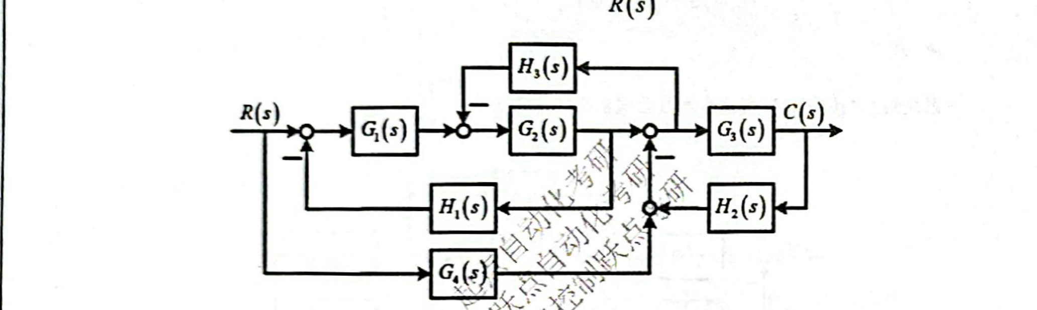
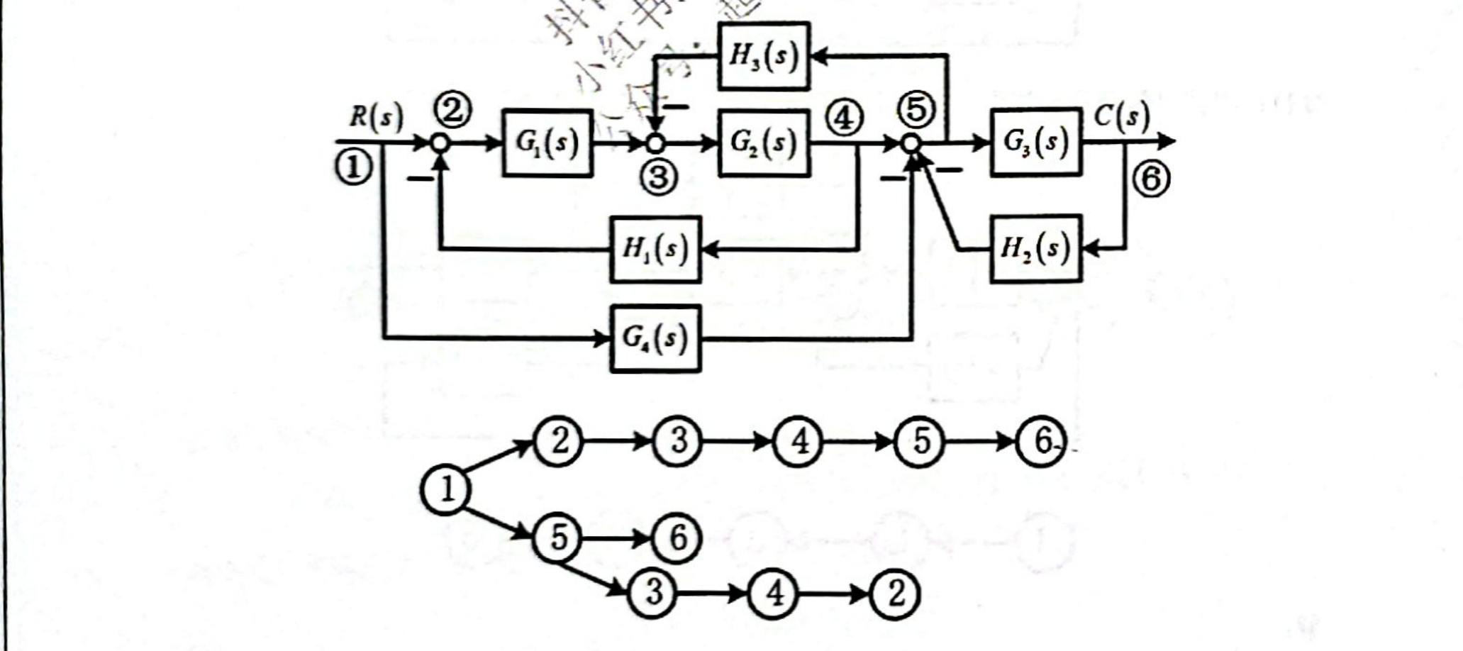
系统结构图如下,试用梅森增益公式求系统传递函数 C(s)R(s)\frac{C(s)}{R(s)}

06-5_p146_fig01.png

分析: 根据“信号分支法”寻找前向通路与回路(该部分不体现在答案中)

06-5_p146_fig02.png

解:

单独回路有三个,即 L1=G3(s)H2(s),L2=G1(s)G2(s)H1(s),L3=G2(s)H3(s)L_1 = -G_3(s)H_2(s), \quad L_2 = -G_1(s)G_2(s)H_1(s), \quad L_3 = -G_2(s)H_3(s)

两个互不接触的回路有一组,即 L1L2L_1 L_2

信号流图的特征式为

Δ=1(L1+L2+L3)+L1L2=1+G3(s)H2(s)+G1(s)G2(s)H1(s)+G2(s)H3(s)+G1(s)G2(s)G3(s)H1(s)H2(s)\begin{aligned} \Delta &= 1 - (L_1 + L_2 + L_3) + L_1 L_2 \\ &= 1 + G_3(s)H_2(s) + G_1(s)G_2(s)H_1(s) + G_2(s)H_3(s) + G_1(s)G_2(s)G_3(s)H_1(s)H_2(s) \end{aligned}

前向通路增益及其余因子式分别为

P1=G1(s)G2(s)G3(s),Δ1=1P2=G3(s)G4(s),Δ2=1+G1(s)G2(s)H1(s)\begin{aligned} P_1 &= G_1(s)G_2(s)G_3(s), & \Delta_1 &= 1 \\ P_2 &= -G_3(s)G_4(s), & \Delta_2 &= 1 + G_1(s)G_2(s)H_1(s) \end{aligned}

系统的传递函数为

C(s)R(s)=P1Δ1+P2Δ2Δ=G1(s)G2(s)G3(s)G3(s)G4(s)G1(s)G2(s)G3(s)G4(s)H1(s)1+G3(s)H2(s)+G1(s)G2(s)H1(s)+G2(s)H3(s)+G1(s)G2(s)G3(s)H1(s)H2(s)\begin{aligned} \frac{C(s)}{R(s)} &= \frac{P_1\Delta_1 + P_2\Delta_2}{\Delta} \\ &= \frac{G_1(s)G_2(s)G_3(s) - G_3(s)G_4(s) - G_1(s)G_2(s)G_3(s)G_4(s)H_1(s)}{1 + G_3(s)H_2(s) + G_1(s)G_2(s)H_1(s) + G_2(s)H_3(s) + G_1(s)G_2(s)G_3(s)H_1(s)H_2(s)} \end{aligned}

总结

  • 梅森增益公式
    • 在信号流图中,应用梅森增益公式可直接求取从源节点到阱节点的传递函数。
    • 结构图与信号流图除去记号体系不同以外,并没有实质的差别,因此梅森增益公式也可直接用于系统结构图。

Discussion

Comments

Post

Thoughts, corrections, and follow-up notes are welcome here.